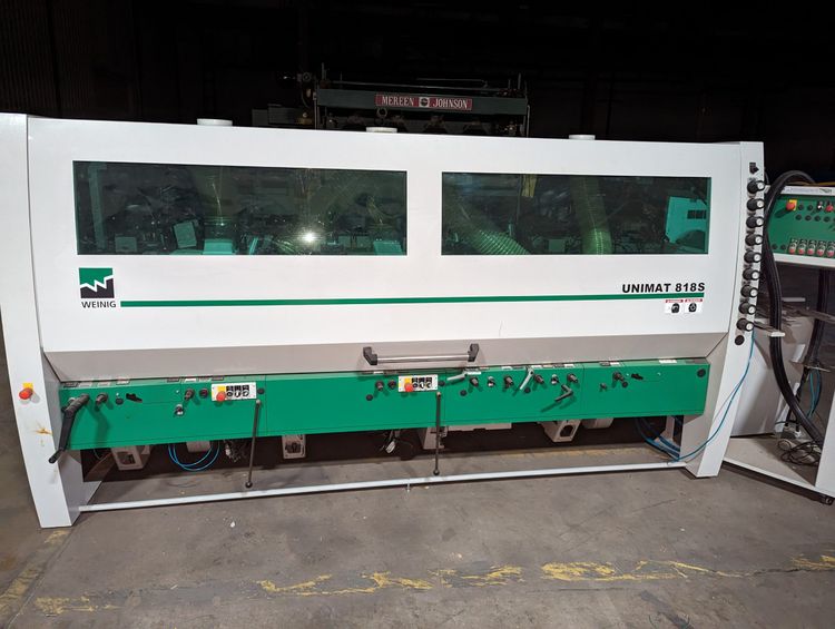
Weinig UNIMAT 818 S
AMERICA North (USA-Canada-Mexico)
Feed Through Moulder 6-Head (B-R-L-T-T-B)
Working dimension 12-3/16″ x 6- 5/16″.
Capacity:
Working width 3/4″ – 12-3/16″
Working thickness 5/16″ – 6-5/16″ — feed speed-variable with 10 HP inverter 20 – 200 FPM
Head sequence: — Bottom 25 HP, right 15 HP, left 15 HP, top 30 HP, top 30 HP, and bottom 30 HP motor; all motors with electronic spindle brakes.
Spindle dia. 1-13/16″ with cutter head speed of 6,000 RPM; — outboard bearings on spindles #1, #4, #5 & #6.
Electronic LED digital readouts for all spindles
Jointer: — Head # 1 Bottom straight jointer manual, remotely controllable with closed safety hood
Automatic stone adjustment; Maximum jointing width 12 -1/16″
With outboard bearing 4 3/4″
For tool circle 6 1/16″- 7-1/16″ — Head # 2 Right spindle Profile jointer automatic
For working height 4-3/4″
Remotely controllable with closed safety hood
Automatic stone adjustment — Head # 3 Left spindle Profile jointer automatic; For working height 4-3/4″
Remotely controllable with closed safety hood
Automatic stone adjustment — Head # 4 Top spindle straight jointer manual; remotely controllable with closed safety hood
Automatic stone adjustment
Maximum jointing width 12 1/16″
With outboard bearing 4-3/4″
For tool circle 6-1/16″- 7-1/16″Profile Jointer automatic
Remotely controllable with closed safety hood
Automatic stone adjustment
Maximum jointing width 9-1/16″ without outboard bearing 4-3/4″ — Head # 5 Bottom spindle straight jointer manual;
remotely controllable with closed safety hood
Automatic stone adjustment
Maximum jointing width 12-1/16″
With outboard bearing 4-3/4″
For tool circle 6 1/16″- 7-1/16″Profile Jointer automatic
Remotely controllable with closed safety hood
Automatic stone adjustment
Maximum jointing width 9-1/16″ without outboard bearing 4-3/4″
— (4) Jointer cassettes for profile jointer, length 6″
— (2) Jointer cassettes for profile jointer, length 9″
— (1) Set of jointing stone
Readouts: — Digiset (double mechanical readouts) for left and top radial adjustments.
One readout is for the tool size and the other for the finished wood dimension (with Imperial inch adjustment
Mechanical readouts on all other axes.
Side pressure roller:
(10) Driven feed roller shaft from above
(5) Driven steel rollers in the machine table
Axial setting range of the feed rollers opposite left spindle, 1-3/8″
Extension of the feed shaft opposite the left spindle to 8 -1/4 in.
Axial setting range of vertical spindle 3-1/8 in. Axial setting range of horizontal spindle 1 -3/4 in. (1st bottom 3/8 in.)
All spindles diameter 1 -13/16″
(6) Additional set of spacing collars, clamping length 6-11/16″, diameter 1-13/16″
Pressure shoe in front of 1st left spindle receding from tool, incl. lateral roller pressure, pneumatic
Receding chip breaker in front of 1st top spindle, pneumatic.
Pressure shoe in front of and guide after top spindle with mechanical digital displays

